| |
|
| tutorials |
| Small
multichannel rendering tutorial | Realsoft
3D 4.5 - Page 2
Tutorial by Tim
Borgmann of (BT)Grafik.
His website link HERE.
(continued from Page
1) ...
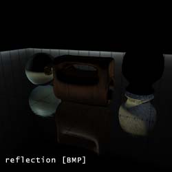
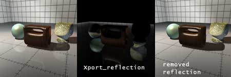
STEP 4 [the reflection]
 |
To export the reflection [fig
09]:
- select the ground material and
open the properties window
- go to the secondary ray
shader, here you will find the
definition to fade the reflection
with distance
- Now add a new 'operation'
type='multiply' and use the
following in- and output channels:
input0 = surface: Color
input1 = traced ray: Illumination
output = Surface: Xport_reflection
- To remove the reflection from
the raytraced image use a 'constant'
with value = 0 and output
= 'Traced ray: Illumination'
Do these steps with all materials
containing reflection information
(in this scene 'ground', 'metallic02'
and 'finished_wood02')
What happens here?
We use the secondary ray shader
to access the traced ray illumination
which is the information we see as
reflection(Illumination) in the traced
image. We multipy this information
with the surface color to get a 'tinted'
reflection color as it can be seen
in the raytraced image and store this
data in our channel. After that we
have to disable the reflection in
the raytraced image because we want
to replace the reflection information
later in post editing, so we can use
a constant value = 0 to define the
illumination of traced reflection
= 0, which means it does not appear
in the finished image.
|
STEP 5 [the depth]
 |
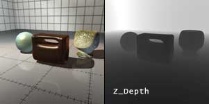
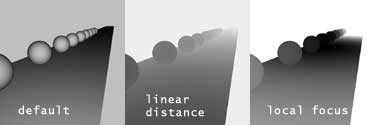
Now the depth pass:
This is really a little bit tricky
and there are two solutions to get
the information.
If we want to use the depth information
as a linear depth which means from
camera to object increasing depth
(for example to add Fog in post editing)
we can use the following steps (this
is a little bit WIP, I'm working on
a better solution):
- Create a new material
and rename it z_depth
- create a surface properties
shader
- drop in a 'copy' object
with source = 'Surface: Distance'
and destination = 'Surface:
Z_depth' [fig
10]
- create a default mapping
in the root level of your
scene with this material
- Now we store the depth information
in the Z_Depth channel, but there
is a problem because an image
data range (greyscale) is from
0 (Black) to 1 (White) and our
depth channel contains information
above 1 because the distance is
in absolute space. This means
an object which is for example
in 100 meters distance of the
camera will store this 100 value
into the channel which can cannot
be seen in the final image, because
everything above 1 will appear
white. (see
illustration)
- So now a little rough trick
to scale this value:
- First you have to check the
maximal distance between your
camera and your objects, which
is in this scene around 3,5 meters
- Now create a new VSL post
image effect and rename it
'z_scale' [fig
11]
- Drop a Float variable
inside the image processing
shader and rename it max_distance,
check the initialize checkbox
and type '3,5' into the
intial value field
- Now drop in a operation
object and change type to 'max',
go to the General tab and
use the drop down to select the
'/' operator.
- Use input0 = 'image: Z_Depth',
input1 = 'max_distance'
and output = 'image: Z_Depth'
- Important: don't forget
to add this VSL post image
effect to the default effects
post image [fig
12]
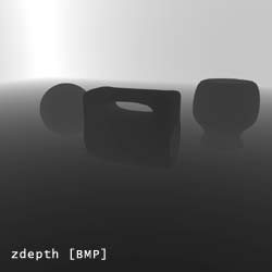
- What this does is the following:
It divides the value of Z_Depth
by the maximum of 3,5 and Z_Depth.
So we scale down the values between
0 and 3,5 to 0 and 1. Everything
above 3,5 meter will appear as
value 1 which means white.
The result will be this:
 |
| 
|
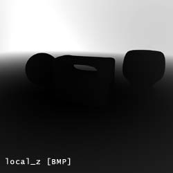
To add a fake DOF in post editing
we need another depth information,
because we don't want the image
to appear linear sharper towards
the camera. We need a channel which
is black around the focus and increase
to white with increasing distance
to the focus:
- Create a new material
and rename it 'local_Z'
- create a surface properties
shader
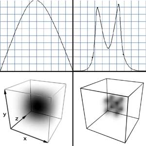
- Now drop in a curve object
with input = 'surface: map
coords' and output = 'surface:
Local_Z'
- modify the curve as shown in
the illustration and change the
input sub channels to x
[fig 13]
- duplicate this curve object
and change operator to *
and subchannel to y
- duplicate this curve object
again and change subchannel
to z
- Because we want the focus appear
black we have to invert the value
with an operation object type
= 1-p1', input = surface: Local_Z
and output = surface: Local_Z
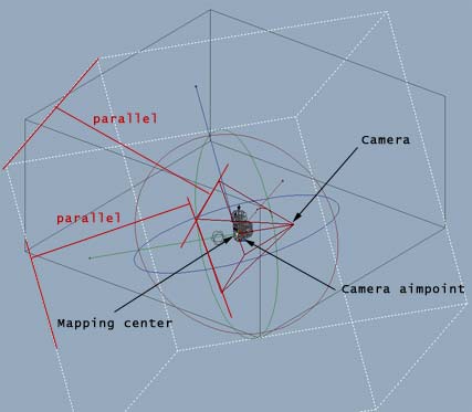
- create a parallel mapping
in the root level (hold
down the shift button while doing
this to create a cube)
- the center of parallel
mapping should be the camera
aimpoint
- now rotate the mapping so it's
parallel to the camera direction
- after doing this you can scale
the mapping so that it surrounds
the scene (Just imagine there
is a sphere inside the mapping
with which we mask our focus).
Everything outside the mapping
will appear complete white in
the final image.
What this does is simple: Because
we use 3 curve objects (one per
axis) we declare a virtual sphere
inside the parallel mapping. At
mapping axis value 0 our curve says
the value is 0, at axis value 0,5
the curve value is 1 and at axis
value 1 the curve value is 0 again.
Because we multiply all values of
the different axis we get white
inside the mapping and black at
it's border. After using the operation
object 1-p1 we invert this values
so the center is black and the border
is white. This is a very useful
technique to create local effects
(like the old local scope in Real
3D V3). You can modify the curves
to get even more interesting effects.
|
STEP 6 [lets render]
STEP 7 [post editing]
  |
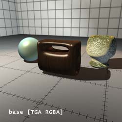
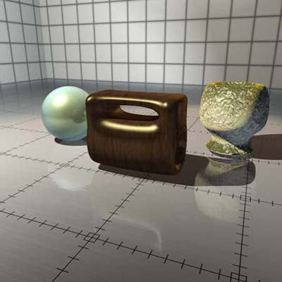
Now we have all this single images
and will use them to create a 'new'
image. For the following steps you
can use for example Photoshop (PS)
- Open all the images in PS
- Select the base.tga and create
a new alpha channel
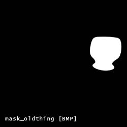
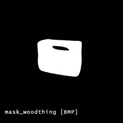
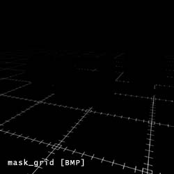
- Now select the mask_ball.bmp,
select all (CRTL+A), copy and
paste it into the new created
alpha channel of base.tga
- Rename this channel to mask_ball
if you want
- Proced this steps with all mask
and depth images until you have
[fig 16]
- Now select the reflection image,
select all, copy and paste it
into a new layer of base.tga.
Change the layer type to negative
multiply or soft light (depends
on what look you want to have).
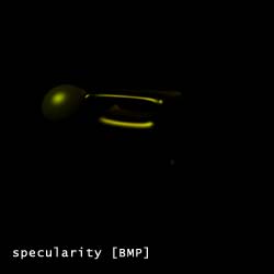
- Do the same with the specularity
image. [fig
17]
Now you are ready to play! Here are
some examples:
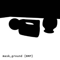
- Blur the reflection channel
and adjust transparency (maybe
use the mask channels, for example
mask_ground, to blur only the
reflection on the ground)
- Try other layer types like multiply,
screen or soft light
- Blur the specularity, play with
the transparency and color adjustment
- Change the color of the different
objects and adjust their levels
- load the zdepth mask, create
a new layer and fill it with a
color to fake fog
- load the local_z mask, maybe
adjust the levels of this mask
before loading, and use a blur
to add some fake DOF
|
|
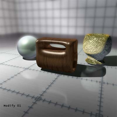
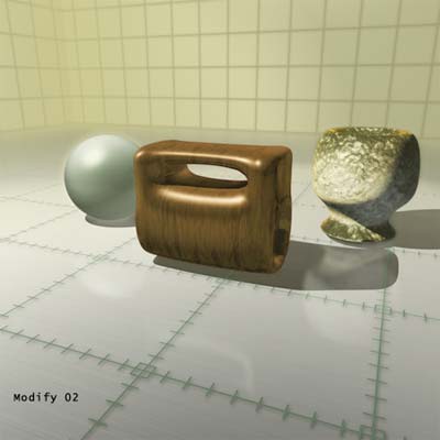
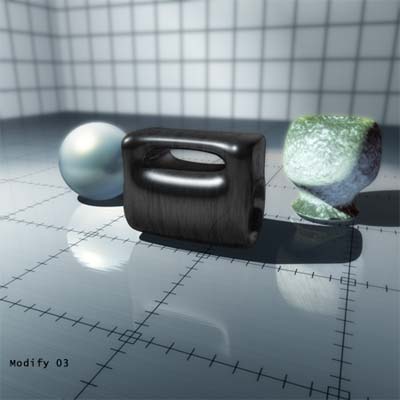
These
are just a few rough examples (shown
in the following images). Be free
in your creativity but be careful
with your modifications, because the
elements of the image play together,
so you can not create a really 'new'
image, but you can change the look
and feeling.
I hope this tutorial helps a little
bit to explore the power of the RS3D
channels. I'm working on a good way
to export shadows now ;-) |
|
| Page
updated on
Tuesday, 25 February, 2003
. For feedback / model submissions or articles
- please email
us. |
|
|