|
|
|
realsoft3d@scenegraphics.com
REALSOFT
SALES AND SUPPORT @ SCENE
|
|
|
|
|
|
|
|
|
|
|
|
 |
|
|
|
|
|
|
|
|
 |
|
 |
|
 |
|
|
 |
|
|
|
|
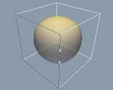
From where the last tutorial left off, run the mouse
cursor over the SDS in edit
mode. Faces are highlighted to show
which face will be selected when
the mouse button is clicked. |
|
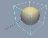
Select the face which corresponds to the left face
relative to your view arrangement.
A handle appears and the face is
highlited. |
|
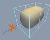
Press the CTRL key and drag on the blue handle to extrude
a face out. You will see that most
common SDS modeling operations are
done using the handles together
with key modifiers. |
|
|
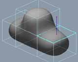
Repeat this process of extruding faces a few more times
to get a very basic car shape. |
|
|
|
|
 |
|
 |
|
 |
|
|
 |
|
|
|
|
|
|
|
|
|
|
|
|
|
|
|
|
|
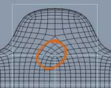
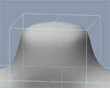
Very important for SDS modeling
-> look at the underlying smooth
nurbs mesh that results from the
SDS control cage. Here we see the
pattern that results from a 'T -
intersection' of edges. |
|
|
|
|
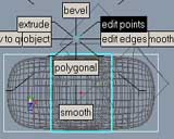
You can quickly change between face/edge and point
editing using the compass menu.
Here is the top view about to go
into point editing to drag a few
points there to get the desired
shape. |
|
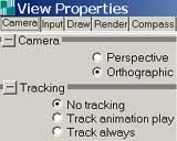
Tip: You may want to go to the view properties and
change some settings for that 'camera'
view that were set up in the last
tutorial, if you prefer modeling
SDS in orthographic views only. |
|
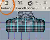
Taking a view from the side of the car, drag-select
faces on the lower half and use
the Tri/Quad tool in the control
bar to subdivide these faces. |
|
|
|
|
|
|
 |
|
 |
|
 |
|
|
|
|
|
|
|
|
|
|
|
|
|
|
|
|
|
|
|
 |
|
|
|
|
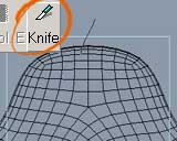
Looking from the side of the model, use the knife tool
from the control bar to split the
edges at the top. |
|
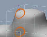
See how the knife tool splits all edges that you draw
through, and creates new edges joining
the intersections. Very useful. |
|
Go into points mode and select the points shown here. |
|
|
Now, again in the control bar, use the ADD tool to
create a new edge between these
selected points. Repeat this process
for the other side of the car. |
|
|
|
|
 |
|
 |
|
 |
|
|
 |
|
|
|
|
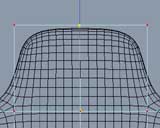
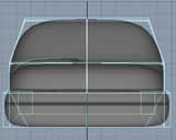
Now look again at the 'flow lines' of the nurbs mesh.
Much more tidy and appropriate for
this part of the model. After some
practice, you will get a good 'feel'
for how to contruct SDS control
cages which result in nurbs meshes
that flow nicely with the contour
of the shape. |
|
 |
|
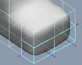
Now to make a simple bumber shape. Select faces shown.
A tip for selecting backfaces without spinning round
to the other side of the model is
to use the comma ',' key while selecting.
It cycles through all faces from
back to front. |
|
|
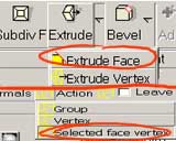
In the control bar, hit the small triangle next to
the extrude tool to get options
for that tool. Select 'Extrude Face',
and under the 'Action' tab, select
'Selected face vertex'. |
|
|
|
|
|
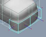
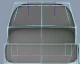
Split the car down the middle using the knife tool
with grid view and snap on. This
gives a little extra detail to play
with. To perform a straight-line
knife uncheck the freehand option
in the toolabar after selecting
knife tool. |
|
|
|
|
|
|
|
 |
|
 |
|
 |
|
|
 |
|
|
|
|
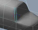
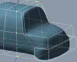
.. and this is the result. The extrude and bevel tools
here are provided when extra control
is needed over just performing those
operations with the handles as was
done previously (with Ctrl-drag
on handle). |
|
Use the compass (same as before) to go into edge mode.
Select the front windshield edge
and bevel it by using crtl-LMB drag
up on the handle endpoint. You
can perform this on both sides at
the same time by selecting both
edges and using bevel on one edge
to get things done faster. |
|
Like you bevelled the edges before, select the faces
on the windshield and bevel those
to give more control over the shape
there. |
|
|
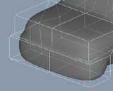
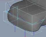
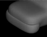
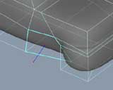
Knife again as shown. Notice how features get a little
sharper as more detail is added
to the SDS cage. The resulting geometry
of all SDS cages is resolved
with clever use of continuous nurbs
patches. |
|
|
|
|
 |
|
 |
|
 |
|
|
|
|
 |
|
|
|
|
|
|
|
|
|
|
|
|
|
|
|
|
|
|
Go back to face mode and select as above - this face
already provides a reasonable starting
point for making the indented wheel
arch. |
|
|
|
There is a very powerful way to achieve sharper definition
to edge/face and points. Each face/edge
and point in Realsofts SDS cage
can be set a weight value. This
is due to the underlying nurbs set
being a complete weighted NURBS
implemetation. Notice here the the
bumber is currently quite smooth
where it joins the main body. |
|
|
|
 |
|
|
|
|
|
|
|
|
Go into edge mode and select all the edges where the
bumber shape meets the car body.
To help with this, the hotkey SHIFT
adds selections, ALT removes,
and SHIFT+CTRL toggles. |
|
|
|
|
|
|
|
|
|
|
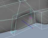
There are a few ways to sharpen at any value you want,
but for now a quick and easy method
to sharpen these edges is just select
the dropdown list in the toolbar
and change from smooth to sharp
Do a quick viewport render - '0'
(zero) shorcut key to see the result
clearly. |
|
|
|
|
|
|
|
 |
|
 |
|
 |
|
|
|
|
 |
|
|
|
|
|
|
|
|
|
|
|
|
|
|
|
|
|
|
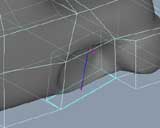
Use the knife tool to make a few new points on this
face close to where the inner part
on the wheel arch is. |
|
|
|
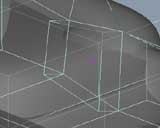
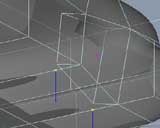
Use CTRL-LMB drag to extrude this face inwards. This
gives nice joining faces at the
sides and top, but leaves us with
some extra faces at the bottom which
have to be fixed up. There's probably
a better way to do this but I chose
to just go ahead and make the extrude
and fix up the details later. So,
to fix up... |
|
 |
|
You will see a huge hole in the mesh now. That's fine.
Look at the bottom and notice that
there is actually another face there
extending to the outer edge of the
car. |
|
|
|
|
|
|
|
|
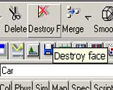
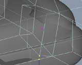
First select this face and destroy it using the tool
shown above. Destroy removes the
face completely, while 'Delete'
will create a new larger joining
face. |
|
|
|
|
|
|
|
|
 |
|
 |
|
 |
|
|
|
|
 |
|
|
|
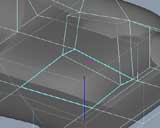
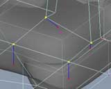
Select points and merge as shown above. The shorcut
key to merge points is SHIFT-M. |
|
'Destroy' the large face at the bottom. |
|
Now you can see that a nice framework of points exist
at the correct place (there were many other ways this could have been done). |
|
|
|
|
|
|
|
|
|
|
|
|
|
|
|
|
|
|
|
|
|
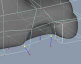
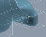
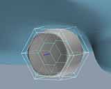
Select the points in a cycle and add a face. |
|
|
|
 |
|
 |
|
 |
|
|
|
|
|
 |
|
|
Basic shape done. |
|
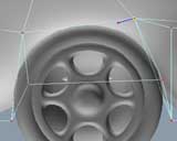
Move a few points around to get the desired shape. |
|
(I won't detail the wheel modelling procedure I used..
it's just using the method I copied
from Hellmut T's wheel tutorial.) |
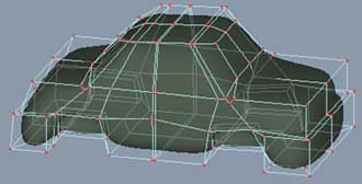
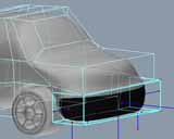
Here's the finished wheel and a few more point adjustments
made to get a nice circular wheel
arch matching the wheel. |
|
|
|
|
|
|
 |
|
|
 |
|
|
|
|
 |
|
|
|
|
For some quick and easy texturing, I just selected
faces and dropped materials straight
into the viewport. Here the standard
rubber has been dropped onto the
bumber faces and is viewed in OGL. |
|
|
|
|
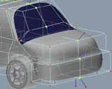
Another onto windshield faces |
|
|
A few more points are added with knife tool, and various
points are moved around to get a
'front' and 'back' for the car. |
|
Version 4.5 provides a mirror tool based on construction
history for modeling opposite sides
at once. This one was just cut in
half, mirrored and joined with the
'join faces' tool. |
|
|
|
|
|
|
|
|
 |
|
 |
|
|
|
 |
|
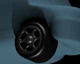
Standard metal and rubber for the wheels and tyres. |
|
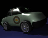
.. and a few more materials to suit your taste.. or
whatever .. |
|
|
|
|
|
|
|
|
|
|
|
|
|
|
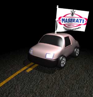
Using the basic SDS car body shape, this variation
adds some nurb modeled trimming
and booleaned-out windows. Nurb
objects can be used to cut out of
SDS shapes & analytics, and
visa-versa quite interchangably. |
|
|
|
|