| Creating
an animated Gas Flame
By Frank
“The Rookie” Dodd
Thanks
to Bernie den Hertog for the gas stove reference
image
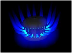
At first glance
creating a gas flame seams like a simple
job to create a simple object, essentially
it is a smokeless burning cone that glows
and flickers about. However to create a
convincing animated gas flame required some
problem solving as we will now see. There
are five steps to this job: -
- Gathering References
- Modeling
- Creating Materials
- Texturing Models
- Animating the model
Gathering References
References images are
essential to creating an accurate model
in a short amount of time, they can either
be photographs of the subject or sketches
you have made by hand. In this case I started
by using a web search engine to scour sites
for images of gas flames (both AltaVista
and Google offer good image search engines)
and Bernie also helped me out with digital
photographs of his gas stove.
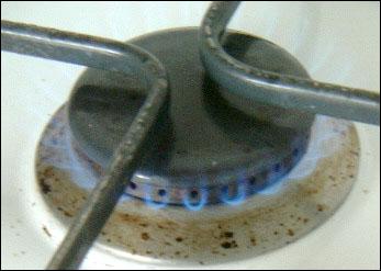
Fig
1: Gas Stove Reference Image
By studying the flames
it could be seen that the flame starts brightly
at the bottom usually a cyan blue, which
quickly fades into a deeper blue before
fading to black. The edges of the flame
had a slightly diffuse blue glow, but still
had a well-defined edge. I used this description
to sketch up some gas flames until I was
happy with the result.
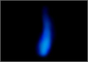
Fig
2: Gas Flame Sketch
Modeling
A gas is usually modeled
with a volumetric object or with particles
to achieve a diffuse shape that changes
as it moves within the air. However as we
have seen a natural gas flame emanating
as a jet has a fairly constant shape and
a visible edge so it could be created as
a model. The flame has a conical shape and
looks good with a slight bulge at its base,
it is also symmetrical so it is a good candidate
for construction by rotating a NURBS curve
about and axis.
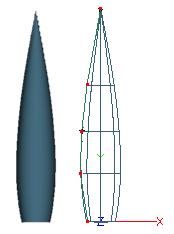
Fig
3: Constructing the model
Creating Materials
There was now a
nicely shaped gray flame shaped blob,
and a material needed to be created that
defined how light interacted with the object
before reflecting into the camera. For a
detailed insight into this process please
refer to David Coombes articles explaining
ray tracing.
Many materials can be created by using existing
materials as a template or by using the
built-in wizards. This material was created
from scratch though by selecting the menu
option New VSL Material.
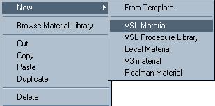
Fig
4: Creating a new VSL material
First the colour of the
material was defined, as we said the flame
is cyan at the bottom and as we go upward
it turns a rich blue a simple way to define
this is with a VSL curve object. Colour
is a property of the surface and so a surface
property shader was added followed by a
curve object.

Fig
5: Adding shaders
The colour changes as
it goes up the material so the curve input
needed to be the Y position of the Mapping
Co-ordinates, the higher up the map it goes
the further along the curve it moves. When
it is low down the curve the RGB levels
are set to a nice cyan and as it goes up
the curve the RGB levels become more blue,
the gradient view is very useful when defining
colour.
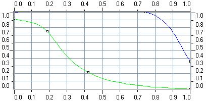
Fig 6: Defining the colour curve
Another property we noticed
was that the flame faded away at the top.
This is another property of the surface
that can be easily define with a curve.
Again the fade changes as it goes up the
material so the curve input was again the
Y position of the Mapping Co-ordinates.
As for the shape of the curve when it is
low down the flame is very visible but as
it gets to the peak it fades to nothing.
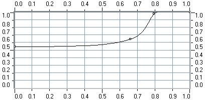
Fig
7: Defining the fade curve
The flame has a blue
glow all around it so some fixed glow was
added to our material with a simple constant
value, a nice rich blue. Another constant
value was used to set the size of the glow.
The settings of all of these parameters
will probably need to be tweaked specifically
for a specific application.
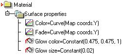
Fig
8: Defining the glow
Finally the geometry
of the model was still illuminated by the
lighting in the scene as can be seen at
the left of figure 9, only a gas flame produces
its own lighting and illuminates itself.
This effect can be created by copying the
colour channel into the illumination channel.
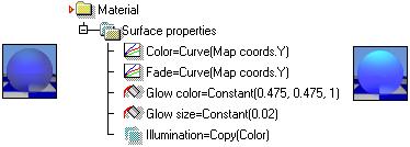
Fig
9: Self illumination
Texturing Models
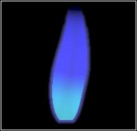
Finally a Geometric model
had been produced and a gas like material
created. Now all that was needed was to
bring the two together to produce a gas
flame. The material was very simply applied
as a default mapping, the mapping following
the contours of the geometric object so
that the fading and colour was applied from
the base of the object working its way upward.
Animating the model
Although scripting was not the only way
to solve the animation problem it was the
most flexible. If you don't feel comfortable
with scripting a similar effect could have
been achieved by creating a choreograph
on the object that animates the objects
scale and then simply create a rapidly changing
curve, this choreograph could even have
been saved and reloaded onto other objects.
However a little investment of time
in creating a script can make life much
easier when you need to re use and subtly
change the animation later.
Gas flames generally tend to flicker, quickly
and randomly changing the size by small
amounts this can be easily simulated by
scaling the object by a small random amount
on each frame. The size of Gas flames can
usually be controlled too for example by
the knob on a Gas stove.
| The best way to approach
most animation problems is often in
the guise of a Real3D
style animation method. An animation
method is an animated level running
a script that uses the objects within
it like parameters for defining the
animation effect. Each method is separate
and unique in how it works and in this
instance any objects dropped into our
Gas Flames method are treated like separate
flames and animated as such, individually
and separately. A slider associated
with the method level will also be used
to scale all of the objects inside it
to create the effect of the Knob on
the Gas Stove |
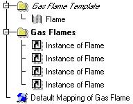
Fig
10: Example Gas Flame Method
|
| I always start by creating
an example structure like figure 10
before I create a script so I know what
I will be working with. Here you can
see in the Example the Gas flame method
and the flames stacked inside it. Once
we are happy with the structure we can
do a little planning of what needs to
be done to create the effect. A quick
way to approach this is with a flowchart,
you can use a program like FlowCharter
or even Microsoft
Word's diagrams to scribble down
jobs that need to be done. |
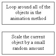
Fig
11: The main things we need to do
|
At this stage you can quickly move the
tasks around and order them, inserting new
items as you find new jobs that need to
be done. Each time thinking through logically
and examining exactly what effect each step
in the process will have on the animation.
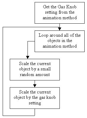
Fig
12: We introduce the idea of the Gas Knob
control
Working through the procedure it seams
to have defined all of the steps needed
to control the animation. We get the gas
knob setting go through all of the objects
scale them randomly and then scale them
again based on the setting of our gas knob.
Once we are happy we can tidy our diagram
up and make the flow between the steps more
clear. Also we should clearly define what
each step is doing. Before it was not clear
how much of a random amount the object was
to be scaled now it is.
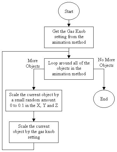
Fig
13: Tidying up the diagram to make its progress
more clear
The easiest way to create a Realsoft
Script from this is to use Building
Blocks translating these steps is
fairly straightforward. First you can use
comments to recreate the diagram inside
the Building
Blocks tool. Then you can enter blocks
beneath the comments to carry out the tasks
that they specify. For more information
on using building
blocks please refer to the tools
manual.

Fig
14: The bare bones program, a framework
to work within
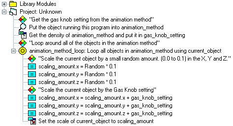
Fig
15: Fleshing out the comments into complete
working blocks
The Final Result
The final result of model,
material and animation worked very well,
especially for smaller images. More detail
would need to be added to the flame if it
was to be rendered at higher resolutions.
This all works as a nice base for an animation
and with a few tweaks it can be useful in
many situations from a gas stove to a jets
after burners.
DivX 4 - 75Kb
Download
the Gas Flame Method
|